
Filters
28 products


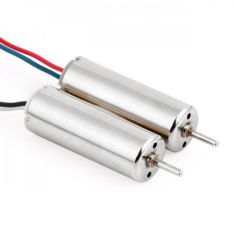
BIR V2 Brushed Motors
Sale priceRs. 336.00
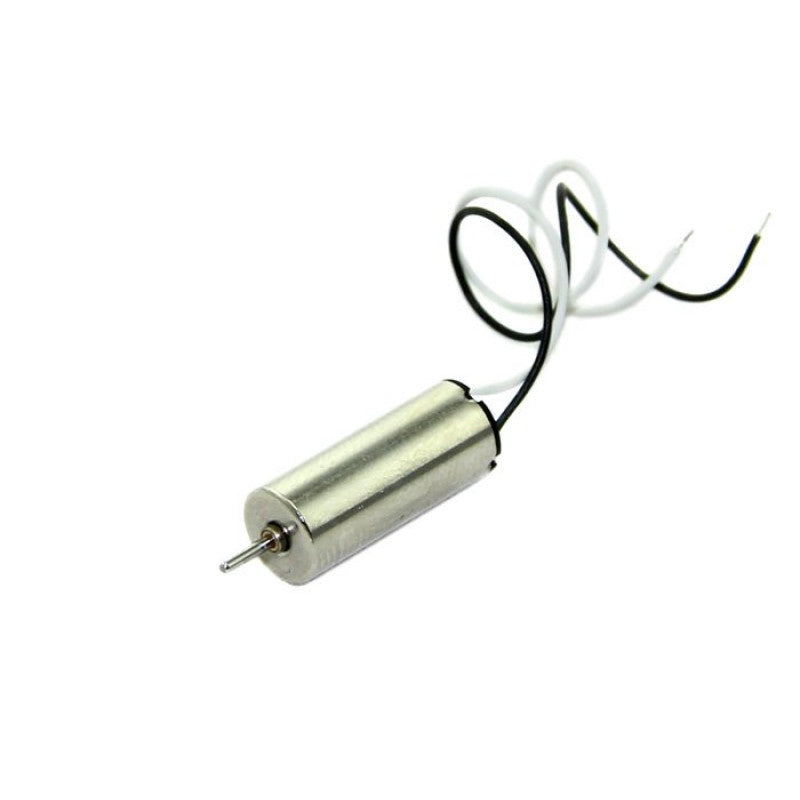
BIR Brushed Motors
Sale priceRs. 199.00
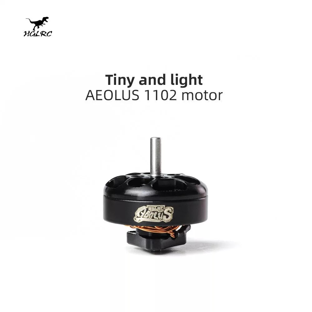
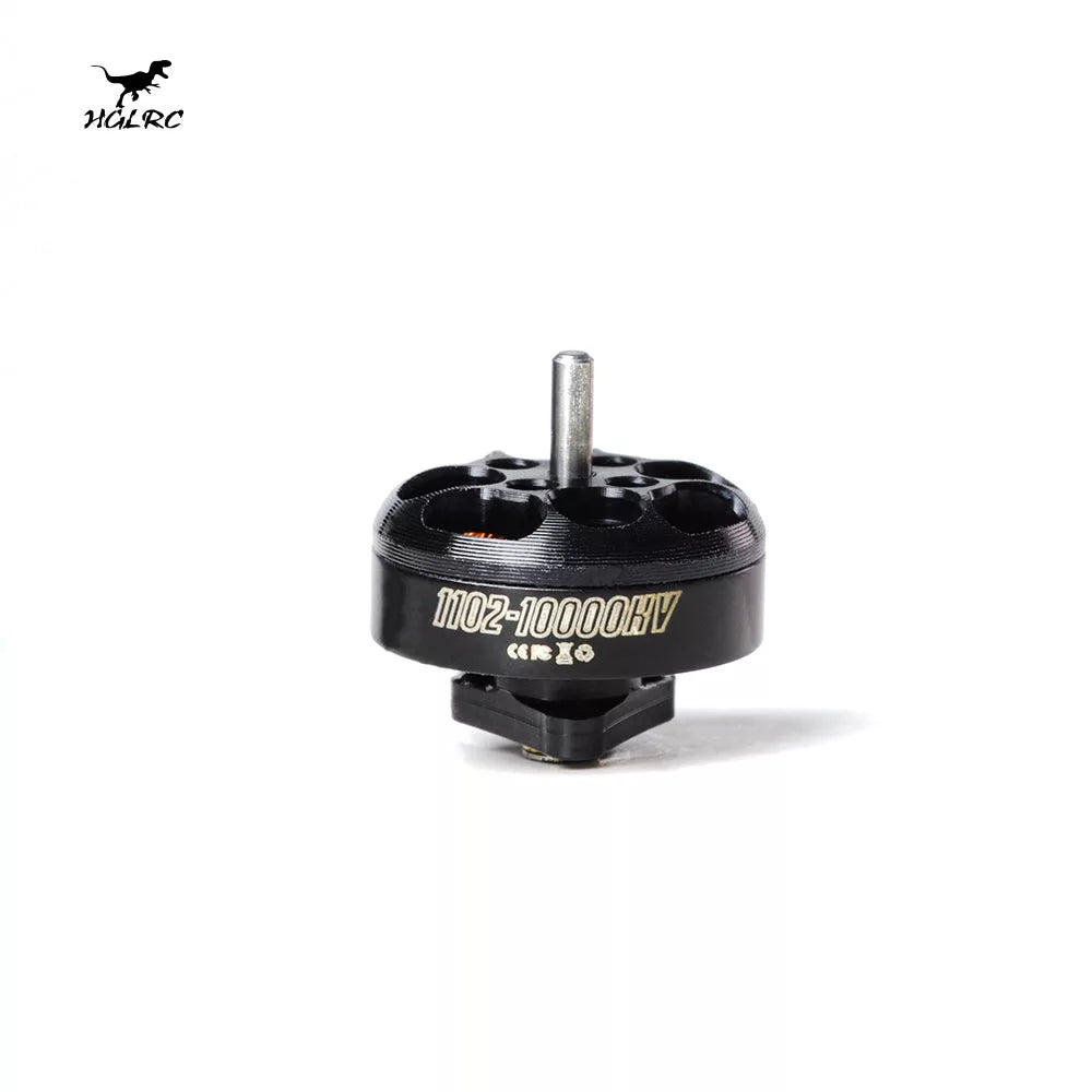
HGLRC AEOLUS 1102 10000KV/18000KV Brushless Motor
Sale priceRs. 1,250.00
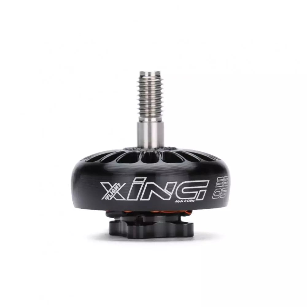
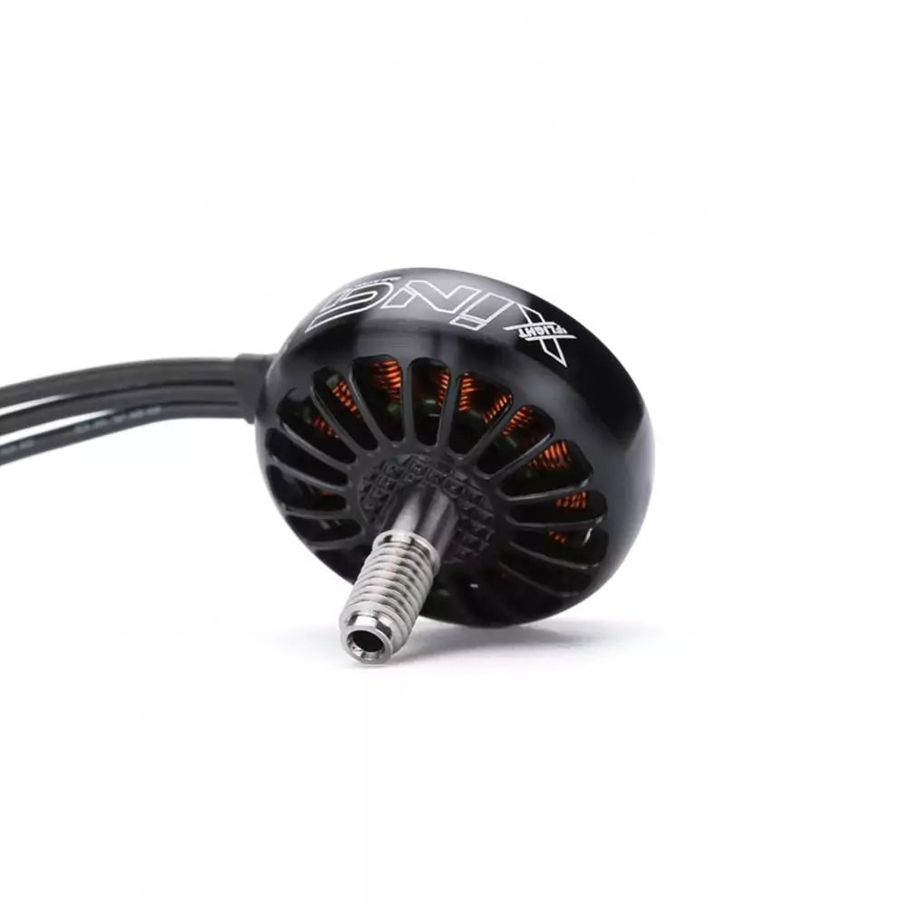
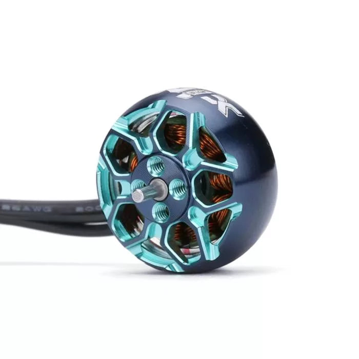
XING 2205 2300KV FPV NextGen Motor - Black
Sale priceRs. 1,778.40
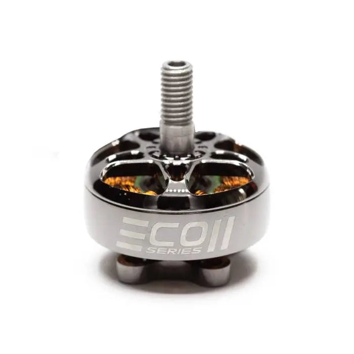
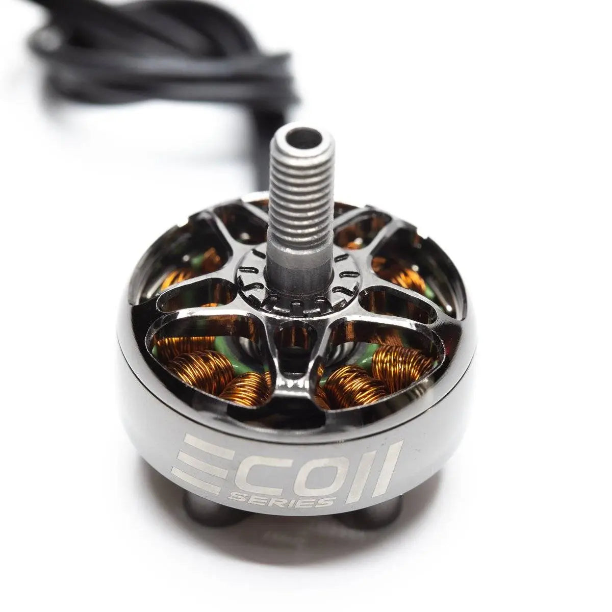
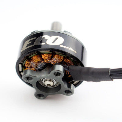
EMAX ECO II Series 2807 Motor 1300KV
Sale priceRs. 2,196.96
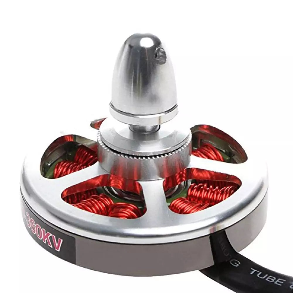
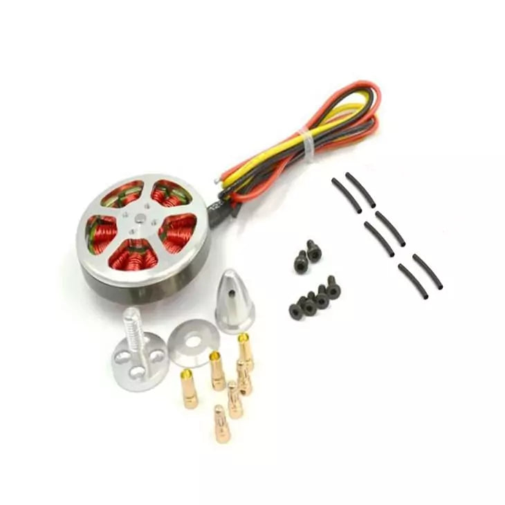
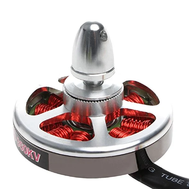
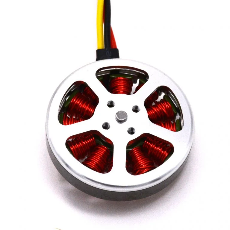
Flycat 5010 360KV High Torque Brushless Motor for Drone
Sale priceRs. 1,500.00

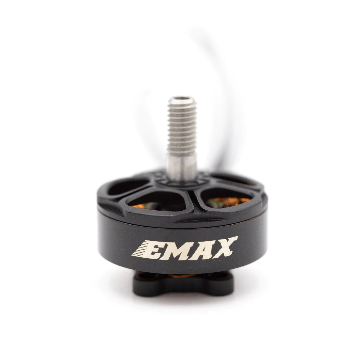
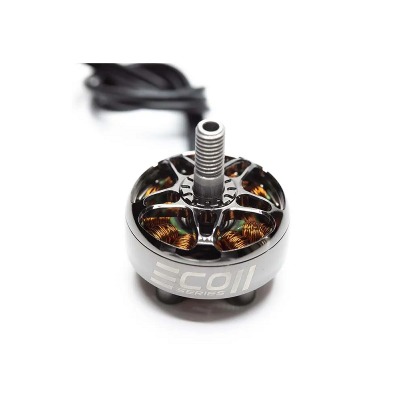
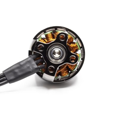
Emax ECO II Series 2207 1700KV Brushless Motor for RC Drone FPV Racing
Sale priceRs. 1,081.60
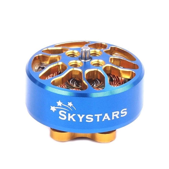
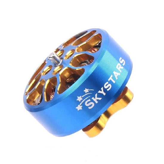
Skystars 1404 3800KV Motor (2 pcs)
Sale priceRs. 1,727.80
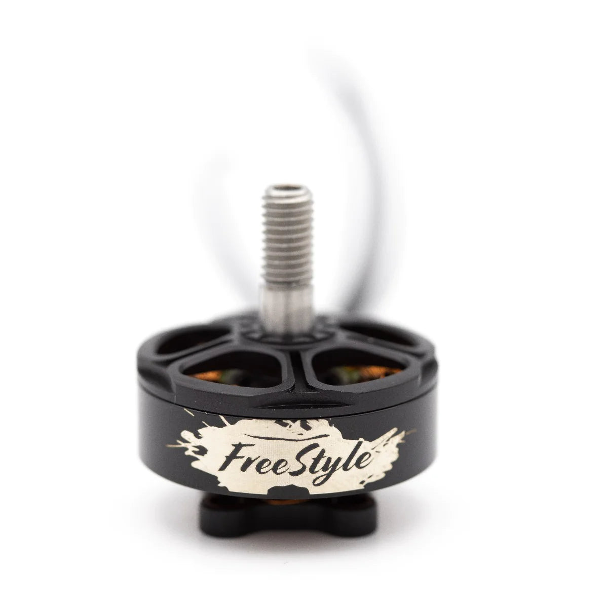
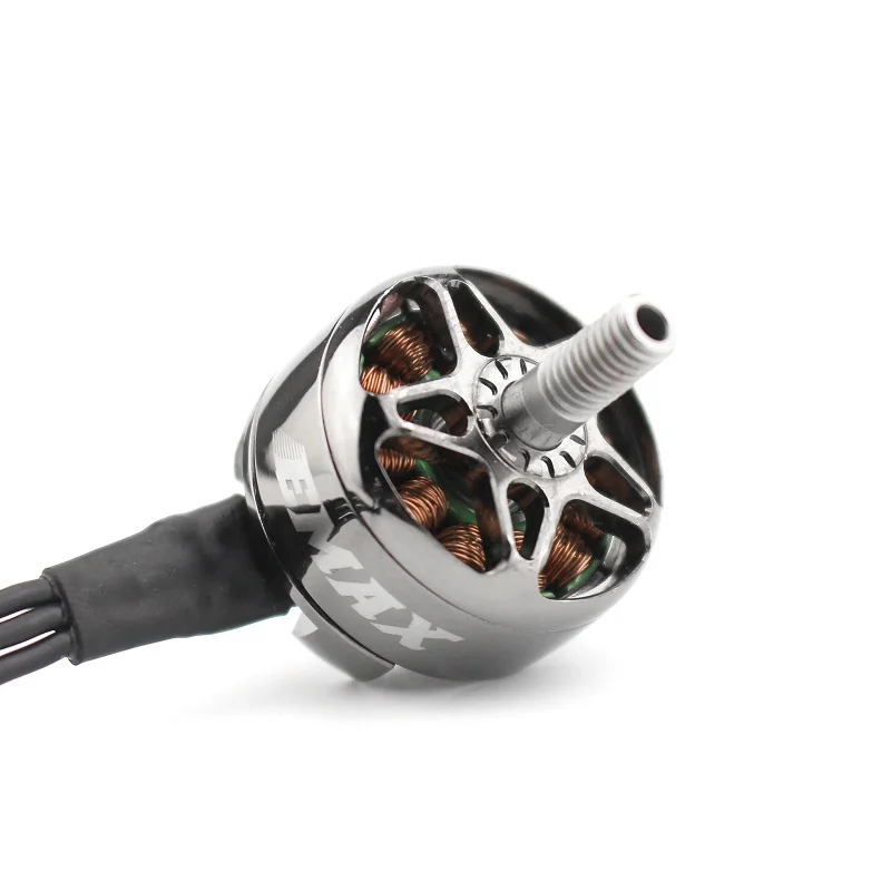
EMAX Free Styles 2306 1700KV
Sale priceRs. 1,714.79
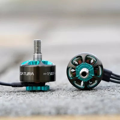
Foxeer Datura 1507 FPV Motor
Sale priceRs. 2,360.80
EMAX ECO 2306 2400KV Motor
Sale priceRs. 1,038.96
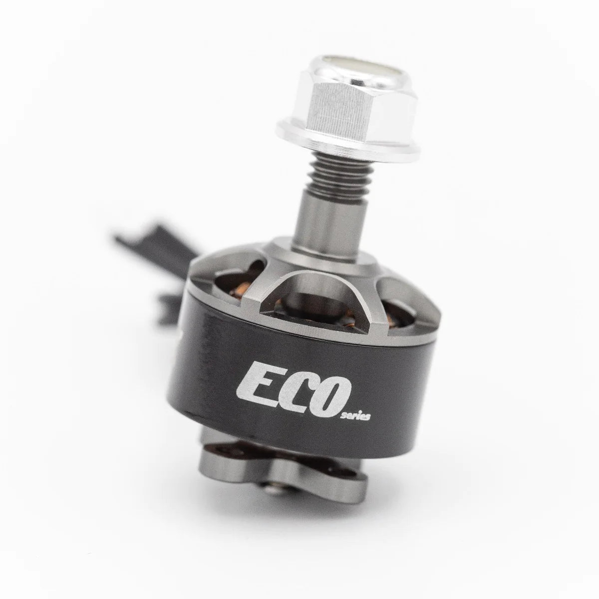
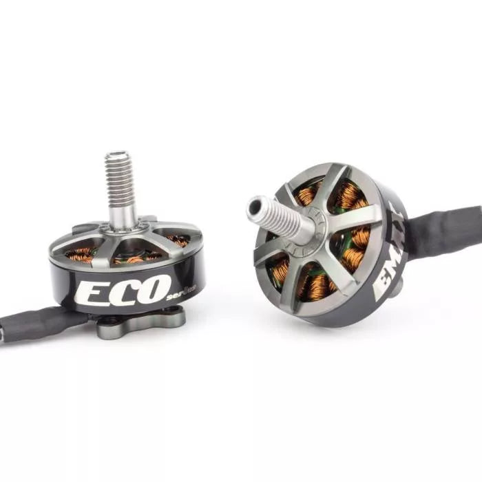
Emax ECO 1407 - 2800kv Brushless Motor
Sale priceRs. 1,154.40


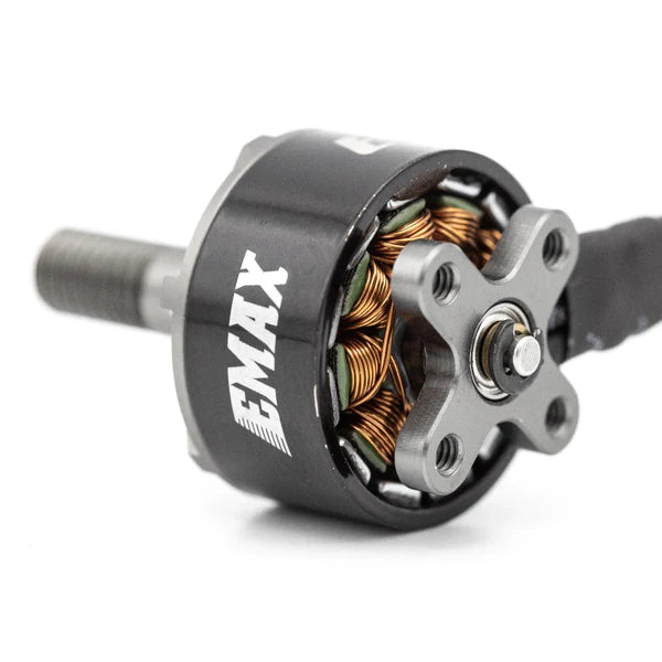
SunnySky E-R2205 2300KV FPV Brushless Motor - CCW Titanium
Sale priceRs. 1,681.00
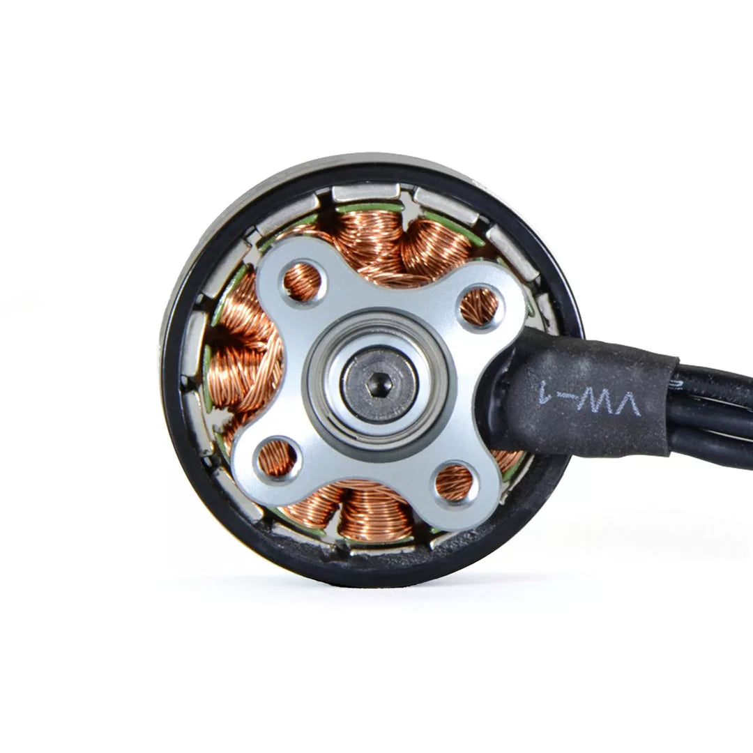
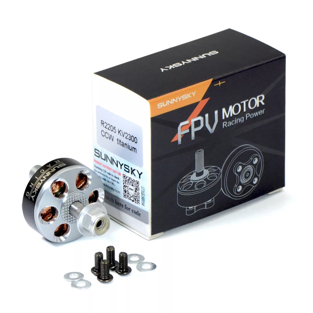
SunnySky E-R2205 2300KV FPV Brushless Motor - CW Titanium
Sale priceRs. 1,681.00
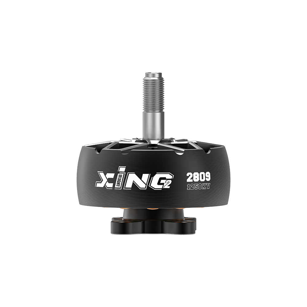
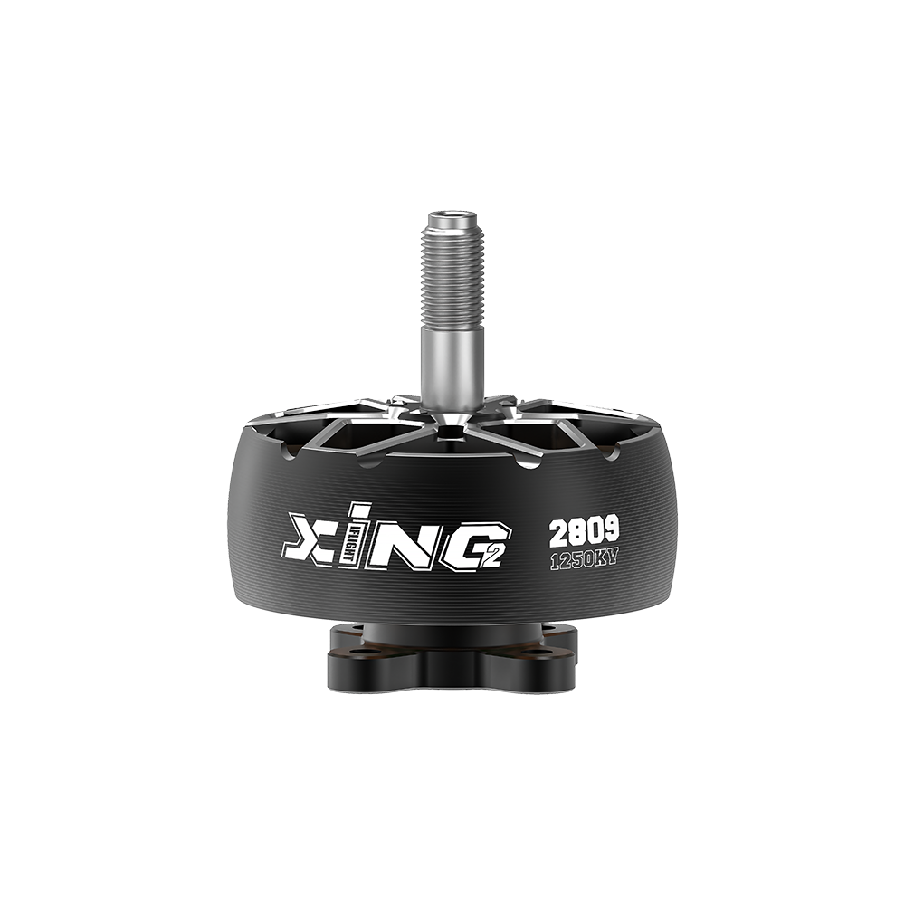
XING2 2809 1250Kv FPV Motor Unibell
Sale priceRs. 4,973.00
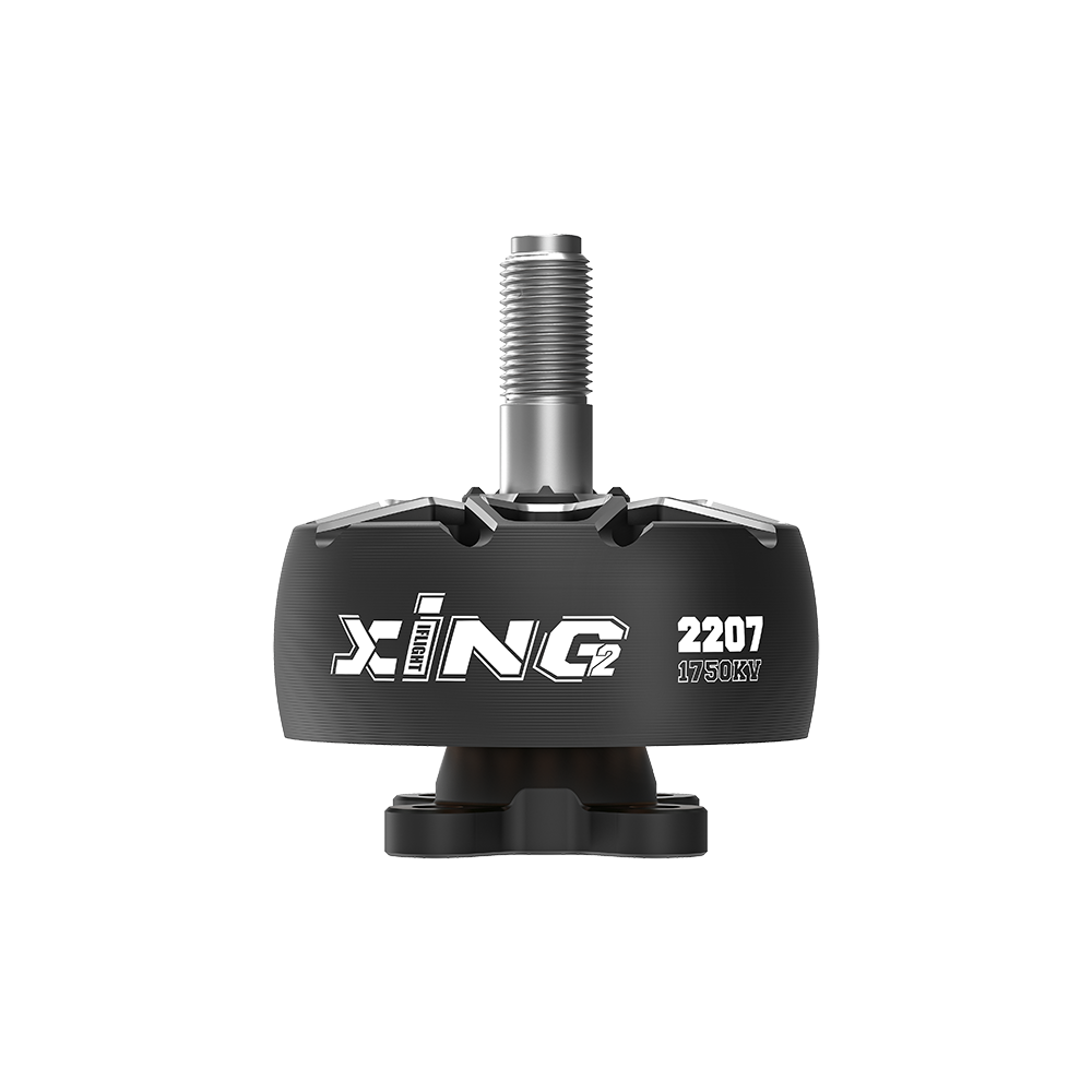
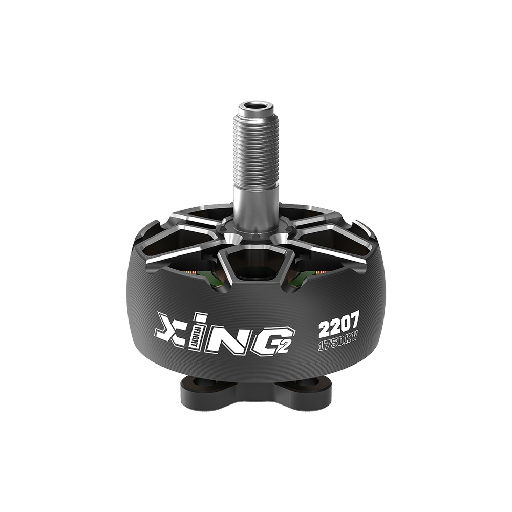
iFlight XING2 2207 1750KV FPV Motor
Sale priceRs. 1,767.00
EMAX ECO II Series 2306 Motor 1700KV
Sale priceRs. 1,867.66

EMAX ECO II Series 2306 Motor 1900KV
Sale priceRs. 1,867.66

EMAX ECO II Series 2207 Motor 1900KV
Sale priceRs. 1,867.66


EMAX ECO II Series 2207 Motor 1700KV
Sale priceRs. 1,867.66


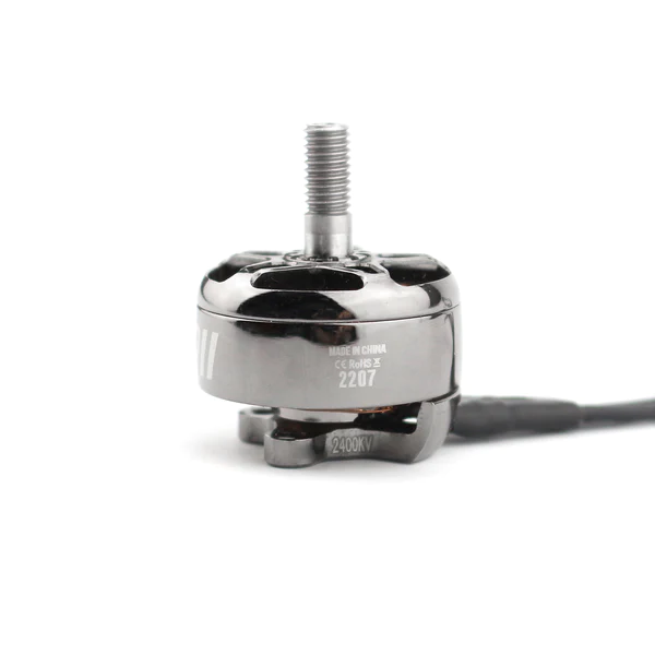
EMAX ECO II Series 2207 Motor 2400KV
Sale priceRs. 1,867.66
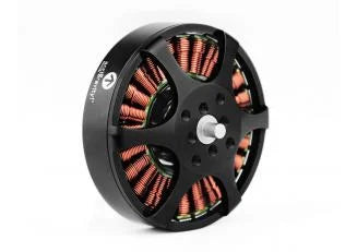
5010 750KV High Torque Brushless Motor for Drone
Sale priceRs. 1,766.96
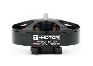
T-Motor Antigravity MN5008 KV340
Sale priceRs. 8,216.00
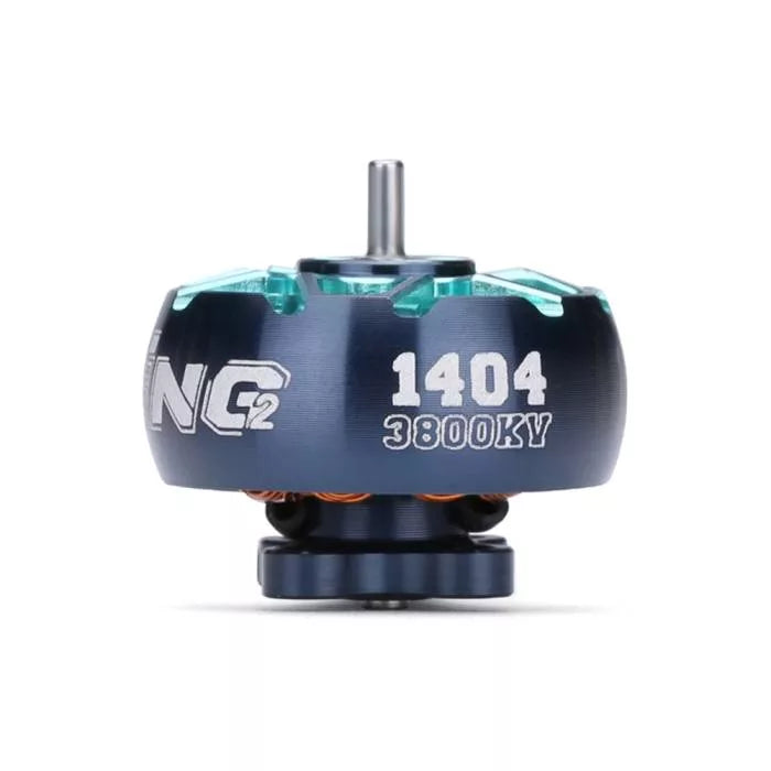
iFlight XING2 1404 4600KV
Sale priceRs. 1,558.96